Introduction to CCNA


 Topology: Physical layout of a network is called topology.


 .00000001.00000000


Default routing: in default routing two routers are used, stub router and transit router.


Comparison RIPv1 and RIPv2:

IS-IS 115
 Switch is a central device for all computers, switch work on datalink layer of OSI model.
Step2: select root port, is a port of Non-root Bridge. Root port will be selected by cost.
CCNA (Cisco Certified Network Associate) 200-120
CISCO:
- American multinational company located in California, USA
- Started in 1984
- Deals with designing, manufacturing, selling, networking equipment
- Also deals with product Certifications
- Inventors of Router
CCNA Exam:
- Code 200-120
- Objective
- Drag & Drop
- Simulations (Lab)
- Mark out of 1000
- Pass mark 825
Interconnection of devices for sharing data or for communication is computer networking.
Types of Network:
- LAN (Local Area Network)
- WAN (Wide Area Network)
- MAN (Metropolitan Area Network)
Ex: Connection of machines in an office or a building and wireless LAN wi-fi.
Requirements of LAN configuration:
- Two of more PCs
- Network operating system
- NIC (Network Interface Card)
- Drivers
- Cables and Connectors
- Protocols
2.WAN: Interconnection of machines in a wide geographical area is called WAN.
Ex: home internet, two Lan connected with a router and a service provider is connected between two Routers, wireless Lan: wan-2G, 3G, 4G.
3.MAN: Administrations of one or more networks by a central authority in between an area of 50 km is called MAN or small WAN.
Ex: wireless MAN-WIMAX
NIC (Network Interface Card): Ethernet card or Network card, NIC is one witch converts network signal into computer language signal, add-on card, integrated built in motherboard.
MAC (Media Access Control): It is unique address stored in NICs, Hardware address or physical address, 48 bits hexadecimal address.
Ex: 00-c0-3u-05-h4-n1
To find MAC address: cmd:- getmac or ipconfig /all
Common Network Devices:
- Repeater
- Hub
- Switch
- Bridge
- Router
- Cloud

2.Hub: Hub is used to connect multiple devices, slow connection, multiple communication is not possible in a time, otherwise collision occurs, normal works only on 10 mbps, works on physical layer.

3. Switch: It is also used to connect multiple devices, there is a MAC address table in switch that it will save MAC addresses of devices and its corresponding ports.
These information are saved on the first time of broadcasting from a port, more faster, multiple communication is possible in a time, reduces collision, normallly work on 10/100/1000/10000...mbps, works on Data link layer.

4. Bridge: Provide connection between LANs, not only do bridge connects LANs they also perform a check on the data to determine whether it should cross the bridge or not, works on Data link layer.

5. Router: Router is used to connect multiple networks, internetwork communication, path selection, packet filtering, packet switching, works on Network layer.
6. Cloud: Cloud is used in diagrams represents where the connection to the internet is.
It also represents all of the devices on the internet.

- Bus
- Ring
- Star
- Hybrid
- Mesh
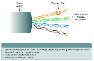
Categories:
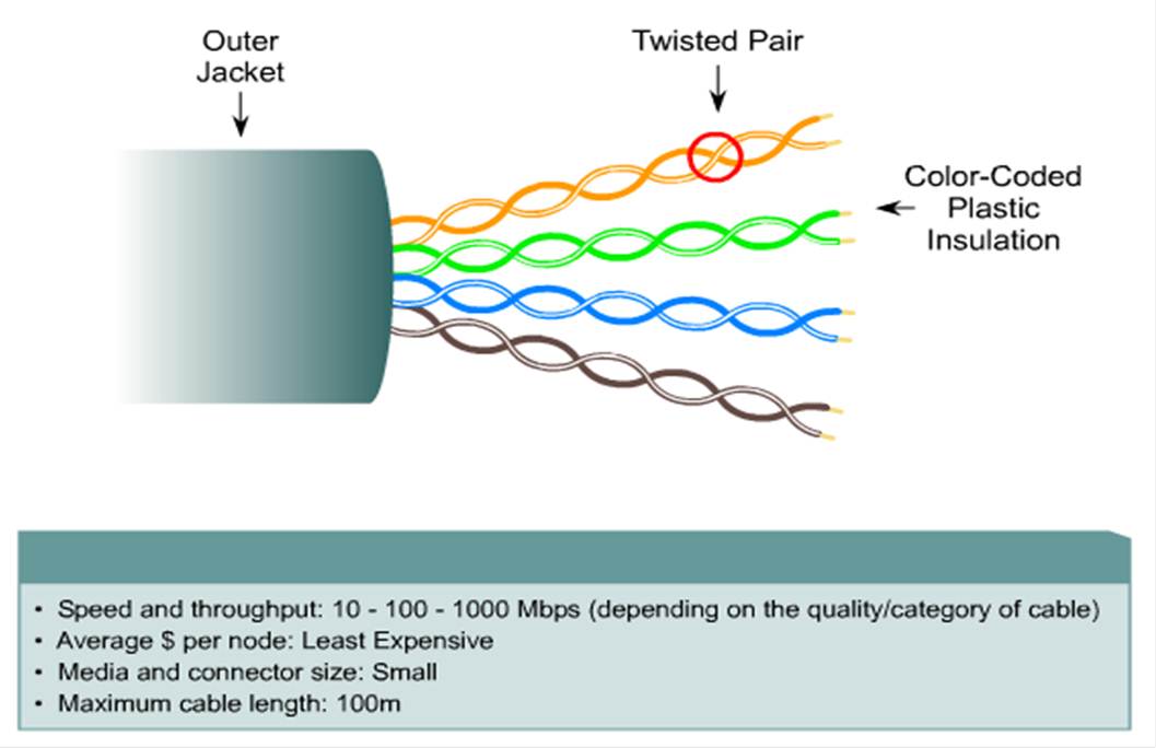
Types of UTP cables:
- Straight through
- Crossover
- Rollover or Console
2. Crossover cable: It is used to connect similar devices such as PC to PC, Switch to Switch, PC to Router, etc.
3. Rollover cable: Rollover of console cable is used to configure Router and Switch.
Color Codes of Straight through Cable:
A Side B Side
White Orange
|
White Orange
|
Orange
|
Orange
|
White Green
|
White Green
|
Blue
|
Blue
|
White Blue
|
White Blue
|
Green
|
Green
|
White Brown
|
White Brown
|
Brown
|
Brown
|
Color Codes of Crossover cable:
A Side B Side
White Orange
|
White Green
|
Orange
|
Green
|
White Green
|
White Orange
|
Blue
|
Blue
|
White Blue
|
White Blue
|
Green
|
Orange
|
White Brown
|
White Brown
|
Brown
|
Brown
|
Color Codes of Rollover cable:
A Side B Side
White Orange
|
Brown
|
Orange
|
White Brown
|
White Green
|
Green
|
Blue
|
White Blue
|
White Blue
|
Blue
|
Green
|
White Green
|
White Brown
|
Orange
|
Brown
|
White orange
|
IPv4 Addresses

IP addresses develop by IETF (Internet Engineering Task
Force).
IP is network layer routed protocol, which are use for
numeric identification of a device on TCP/IP network.
- Binary numeric system: represent data in bits 0 or 1
- Decimal numeric system: represent data in digits, 0-9
- Hexa decimal numeric system: represent data in 0-9 and A-F
Mac address is a hexa decimal format, which consist of 12 hexa
(48 bits). 1 Hexa=4bits. Authorized by IEEE (Institute of Electrical Electronic
Engineering).
- First 6 hexa of Mac address called OUI (Organization Unique Identifier), we can’t change it
- Second 6 hexa of Mac address called vender assign numbers
We have five classes
of IP addresses: A, B, C, D, E
Class A: Range (0-127). Rule: first bit of first byte must be off, at
least one bit from the remaining must be on. Ex: 01000000.
Total network and host in class A:
2n-1, where n=number of network bits. 28-1 -2=27-2=126
(networks).
2P-2, where p=number of
host bits. 224 -2=16777214 (hosts).
Class B: Range (128-191). Rule: first bit of first byte must be
on second bit of first byte must be off, remaining bits may be on or off. Ex:
10111001.
Total network and host in class B:
2n-2, where n=number of network bits. 216-2=214 =16384
(networks).
2P-2, where p=number of
host bits. 216-2=65534 (hosts).
Class C: Range (192-223). Rule: first bit of first byte must be
on second bit of first byte must be on third bit of first byte must be off, at
least the remaining bits may be on or off. Ex: 11010000.
Total network and host in class C:
2n-3, where n=number of network bits. 224-3=221=2097152
(networks).
2P-2, where p=number of
host bits. 28-2=254 (hosts).
Class D: Range (224-239). Use for multicasting, no network and host
portion.
Class E: Range (240-255). Reserved for IETF, use for research
purposes. No network and no host portion.
Subnet mask: Define the network and host portion, in subnet mask on
bits are called network portion and off bits are called host portion.
Ex: 192.168.1.0 255.255.255.0/24
CIDR: (Classless inter domain
routing) or Prefix, /24.
Private and Public IPs
Private IPs: 192.168.0.0-192.168.255.255,
172.16.0.0-172.31.255.255, 10.0.0.0-10.255.255.255. Except these IPs all IPs
are called Public IPs.
Understanding the power of 2: Power of 2 is important to
understand and memorize for use with IP subnetting.
21=2, 22=4, 23=8, 24=16,
25=32, 26=64, 27=128, 28=256, 29=512,
210=1024, 211=2048, 212=4096, 213=8192,
214=16384 etc.
SUBNETTING

Increasing the number of network bits and decreasing the
number of host bits is called subnetting.
Class C: In class c
we can subnet from 1 to 6.
One bit
subnetting: 192.168.0.00000000/25 mask: 255.255.255.128
Total subnets: 21=2. Total host in each subnet: 27-2=126.
We minus last subnet mask value from 256 to find next subnet
id. Ex: 256-128=128. Or Network id+ total host= last IP.
Two bits
subnetting: 192.168.0.00000000/26 mask: 255.255.255.192
Total subnets: 22=4. Total host in each subnet: 26-2=62.
Three bits
subnetting: 192.168.0.00000000/27 mask: 255.255.255.224
Total subnets: 23=8. Total host in each subnet: 25-2=30.
Four bits
subnetting: 192.168.0.00000000/28 mask: 255.255.255.240
Total subnets: 24=16. Total host in each subnet: 24-2=14.
Five bits
subnetting: 192.168.0.00000000/29 mask: 255.255.255.248
Total subnets: 25=32. Total host in each subnet: 23-2=6.
Six bits
subnetting: 192.168.0.00000000/30 mask: 255.255.255.252
Total subnets: 26=64. Total host in each subnet: 22-2=2.
Class B: In class b
we can subnet from 1 to 14.
One bit
subnetting: 172.16.00000000.0/17 mask: 255.255.128.0
Total subnets: 21=2. Total host in each subnet: 215-2=32766.
Two bits
subnetting: 172.16.00000000.0/18 mask: 255.255.192.0
Total subnets: 22=4. Total host in each subnet: 214-2=16382.
Three bits
subnetting: 172.16.00000000.0/19 mask: 255.255.224.0
Total subnets: 23=8. Total host in each subnet: 213-2=8190.
Four bits
subnetting: 172.16.00000000.0/20 mask: 255.255.240.0
Total subnets: 24=16. Total host in each subnet: 212-2=4094.
Five bits
subnetting: 172.16.00000000.0/21 mask: 255.255.248.0
Total subnets: 25=32. Total host in each subnet: 211-2=2046.
Six bits
subnetting: 172.16.00000000.0/22 mask: 255.255.252.0
Total subnets: 26=64. Total host in each subnet: 210-2=1022.
Seven bits
subnetting: 172.16.00000000.0/23 mask: 255.255.254.0
Total subnets: 27=128. Total host in each subnet:
29-2=510.
Eight bits
subnetting: 172.16.00000000.0/24 mask: 255.255.255.0
Total subnets: 28=256. Total host in each subnet:
28-2=254.
Nine bits
subnetting: 172.16.0.00000000/25 mask: 255.255.255.128
Total subnets: 29=512. Total host in each subnet:
27-2=126.
Ten bits
subnetting: 172.16.0.00000000/26 mask: 255.255.255.192
Total subnets: 210=1024. Total host in each
subnet: 26-2=62.
Eleven bits
subnetting: 172.16.0.00000000/27 mask: 255.255.255.224
Total subnets: 211=2048. Total host in each
subnet: 25-2=30.
Twelve bits
subnetting: 172.16.0.00000000/28 mask: 255.255.255.240
Total subnets: 212=4094. Total host in each
subnet: 24-2=14.
Thirteen
bits subnetting:172.16.0.00000000/29 mask: 255.255.255.248
Total subnets: 213=8192. Total host in each
subnet: 23-2=6.
Fourteen bits subnetting:172.16.0.00000000/30
mask: 255.255.255.252
Total subnets: 214=16384. Total host in each
subnet: 22-2=2.
Class A:
In class A we can subnet from 1 to 22.
One bit
subnetting: 10.00000000.0.0/9 mask: 255.128.0.0
Total subnets: 21=2. Total host in each subnet: 223-2=8388606.
Two bits
subnetting: 10.00000000.0.0/10 mask: 255.192.0.0
Total subnets: 22=4. Total host in each subnet: 222-2=4194302.
Three bits subnetting: 10.00000000.0.0/11
mask: 255.224.0.0
Total subnets: 23=8. Total host in each subnet: 221-2=2097150.
Four bits
subnetting: 10.00000000.0.0/12 mask: 255.240.0.0
Total subnets: 24=16. Total host in each subnet: 220-2=1048574.
Five bits
subnetting: 10.00000000.0.0/13 mask: 255.248.0.0
Total subnets: 25=32. Total host in each subnet: 219-2=524286.
Six bits
subnetting: 10.00000000.0.0/14 mask: 255.252.0.0
Total subnets: 26=64. Total host in each subnet: 218-2=262142.
Seven bits
subnetting: 10.00000000.0.0/15 mask: 255.254.0.0
Total subnets: 27=128. Total host in each subnet:
217-2=131070.
Eight bits
subnetting: 10.00000000.0.0/16 mask: 255.255.0.0
Total subnets: 28=256. Total host in each subnet:
216-2=65534.
Nine bits
subnetting: 10.0.00000000.0/17 mask: 255.255.128.0
Total subnets: 29=512. Total host in each subnet:
215-2=32766.
Ten bits
subnetting: 10.0.00000000.0/18 mask: 255.255.192.0
Total subnets: 210=1024. Total host in each
subnet: 214-2=16382.
Eleven bits
subnetting: 10.0.00000000.0/19 mask: 255.255.224.0
Total subnets: 211=2048. Total host in each
subnet: 213-2=8190.
Twelve bits
subnetting: 10.0.00000000.0/20 mask: 255.255.240.0
Total subnets: 212=4096. Total host in each
subnet: 212-2=4094.
Thirteen
bits subnetting:10.0.00000000.0/21 mask: 255.255.248.0
Total subnets: 213=8192. Total host in each
subnet: 211-2=2046.
Fourteen
bits subnetting:10.0.00000000.0/22 mask: 255.255.252.0
Total subnets: 214=16384. Total host in each
subnet: 210-2=1022.
Fifteen bits
subnetting:10.0.00000000.0/23 mask: 255.255.254.0
Total subnets: 215=32768. Total host in each
subnet: 29-2=510.
Sixteen
bits subnetting:10.0.00000000.0/24 mask: 255.255.255.0
Total subnets: 216=65536. Total host in each
subnet: 28-2=254.
Seventeen
bits subnetting:10.0.0.00000000/25 mask: 255.255.255.128
Total subnets: 217=131072. Total host in each
subnet: 27-2=126.
Eighteen
bits subnetting:10.0.0.00000000/26 mask: 255.255.255.192
Total subnets: 218=262144. Total host in each
subnet: 26-2=62.
Nineteen
bits subnetting:10.0.0.00000000/27 mask: 255.255.255.224
Total subnets: 219=524288. Total host in each
subnet: 25-2=30.
Twenty bits
subnetting: 10.0.0.00000000/28 mask: 255.255.255.240
Total subnets: 220=1048576. Total host in each
subnet: 24-2=14.
Twenty one bits subnetting:10.0.0.00000000/29
mask: 255.255.255.248
Total subnets: 221=2097152. Total host in each
subnet: 23-2=6.
Twenty two bits subnetting:10.0.0.00000000/30 mask:
255.255.255.252
Total
subnets: 222=4194304. Total host in each subnet: 22-2=2.
VLSM(Variable length subnet mask)

VLSM is a process of dividing the network into different
network having variable length subnet mask is called VLSM.
Ex: we need public IPs to three offices in country one is the
main office in KLD and other two are branches of main office in KLP and KLJ.
124 IPs for KLD, 57 IPs for KLJ, 27 IPs for KLP.
Now we perform VLSM in 200.0.0.0/24 255.255.255.0 network.
200.0.0.00000000/25 mask: 255.255.255.128
Total subnets: 21=2. Total host in each subnet: 27-2=126.
Network ID: 200.0.0.0/25 mask: 255.255.255.128 we give it to
Kabul.
1st IP: 200.0.0.1 === last IP: 200.0.0.126 ===
broadcast IP: 200.0.0.127 (end of Kabul IPs).
N/2 ID: 200.0.0.128/25 === 1st IP: 200.0.0.129 ===
last IP: 200.0.0.254 === broadcast IP: 200.0.0.255.
200.0.0.00000000/26 mask: 255.255.255.192
Total subnets: 22=4. Total host in each subnet: 26-2=62.
Network: 200.0.0.0/26 mask: 255.255.255.192 === 1st
IP: 200.0.0.1 === last IP: 200.0.0.62 === broadcast IP: 200.0.0.63 === N/w ID:
200.0.0.64 === 1st IP: 200.0.0.65 === last IP: 200.0.0.126 === broadcast
IP: 200.0.0.127 === (we give this network to KLJ office) N/W ID: 200.0.0.128
mask: 255.255.255.192 === 1st IP: 200.0.0.129 === last IP:
200.0.0.190 === broadcast IP: 200.0.0.191 (end of KLJ IPs) === N/W ID:
200.0.0.192 === 1st IP: 200.0.0.193 === last IP: 200.0.0.254 ===
broadcast IP: 200.0.0.255.
200.0.0.00000000/27 mask: 255.255.255.224
Total subnets: 23=8. Total host in each network: 25-2=30.
Network: 200.0.0.0/27 mask: 255.255.255.224 === 1st
IP: 200.0.0.1 === last IP: 200.0.0.30 === broadcast IP: 200.0.0.31 === N/W ID:
200.0.0.32 === 1st IP: 200.0.0.33 === last IP: 200.0.0.62 ===
broadcast IP: 200.0.0.63 === N/W ID: 200.0.0.64 === 1st IP:
200.0.0.65 === last IP: 200.0.0.94 === broadcast IP: 200.0.0.95 === N/W ID:
200.0.0.96 === 1st IP: 200.0.0.97 === last IP: 200.0.0.126 ===
broadcast IP: 200.0.0.127 === N/W ID: 200.0.0.128 === 1st IP:
200.0.0.129 === last IP: 200.0.0.158 === broadcast IP: 200.0.0.159 === N/W ID:
200.0.0.160 === 1st IP: 200.0.0.161 === last IP: 200.0.0.190 ===
broadcast IP: 200.0.0.191 === (we give this network ID to KLP office)N/W ID:
200.0.0.192 mask: 255.255.255.224 === 1st IP: 200.0.0.193 === last
IP: 200.0.0.222 === broadcast IP: 200.0.0.223( end of KLP IPs) === N/W ID: 200.0.0.224
=== 1st IP: 200.0.0.254 === last IP: 254 === broadcast IP: 255.
KLD Network ID: 200.0.0.0 mask: 255.255.255.128
KLJ Network ID: 200.0.0.128 mask: 255.255.255.192
KLP Network ID: 200.0.0.192 mask: 255.255.255.224
Summarization & Wildcard Mask

We can summarize the contiguous blocks of addresses in the
power of two. Ex: 2, 4, 6, 8, etc. but we can’t summarize noncontiguous blocks
network.
172.16.1.0/24
172.16.2.0/24
172.16.3.0/24
===
172.16.15.0/24
172 = 10101100
16 =
00010000
.00000010.00000000
.00000011.00000000
.00001111.00000000
Network portion bits + similar bits. 8+8+4=20. 172.16.1.0/20
summarized.
Wild card mask:
Wild card mask is opposite to subnet mask. Define the network
of host portion. In wild card on bits are called host portion and off bits are
called network portion.
To find wild card mask, we minus known subnet mask from
255.255.255.255.
Ex: 255.255.255.255-255.255.255.192=0.0.0.63
Introduction to Router

Router is a
device which route the packet across different networks.
Router works
on layer3 (network layer).
Router
performs four functions, which are packet filtering, packet switching, path
selection and internetwork communication.
IOS: internetwork operating system. IOS is
an operating system which runs CISCO routers and switches. It is CISCO
proprietary IOS.
RAM: Current
configurations are store in ram.
NVRAM:
Startup configurations are store in nvram. (non volatile, non changeable).
FLASH: IOS
are store in flash.
ROM:
Minuring of IOS are store in rom.
Router
boot process:
Step1: Post
(power on self test).
Step2: Boot
up/operating system or loading IOS from flash.
Step3: Stop
for some time (checking nvram).
Step4: Setup
mode/dialogue/auto configuration mode, starts yes no questions to configure.
Router
configuration:
Console port
+ computer com port (communication, open putty software then select serial and
open.
Router
prompt modes:
Router>:
user mode. Here we can’t give any commands only enable. Enable (from this command it come to privilege
mode.
Router#:
privilege mode. Here we check network connectivity and show command. Configure terminal (from this command it come to
global configuration mode.
Router(config)#:
global mode. Here we can give any configuration commands. To go pervious, CTRL+Z, exit or end.
Password: 1. Plain password. 2. Secret password.
- Plain password: stores password in plain text form
- Secret password: store password in encrypted form
To delete
password: Router(config)#no enable secret or password.
Show
commands:
Router# show
running-configuration (shows current configurations).
Router# show
startup configuration (shows nvram configurations).
Router# show
clock (shows current time and date).
Router# show
history (shows given command list).
Router# show
version (shows version of IOS).
Router# show
flash (shows where IOS are stored).
Router# show
ip interface brief (shows given ip addresses to interface).
Router# show
controllers (shows DTE and DCE sides clock rate).
Different
lines use to configure Router:
Console line
0 = 1. Auxiary line (aux) 0 = 1. Virtual terminal (vty) 0 4 = 5.
- Console line:
Router(config)#
line console 0
Router(config-line)#
password corvit
Router(config-line)# exec-timeout 10
Router(config)#
login
- Auxiliary line:
Router(config)#
line aux 0
Router(config-line)#
password ccna
Router(config)#
login
Virtual
terminal line (vty):
Router(config)#
line vty 0 4
Router(config-line)#
password ccnp
Router(config)#
login
Note: all
these passwords stores in plain text form so by service password-encryption
command it will encrypt all running and future passwords. Ex: Router(config)#
service password-encryption.
Routing
Routing is a
process to define path toward destination network.
Router is
responsible for routing. Routing process work on layer3 (network layer).
Routing
table: In routing table network ID of networks are stores.
Types of
routing: Static
routing, Default routing, Dynamic routing.
Static routing and default routing done by
administrator.
Dynamic
routing uses different routing protocols. Ex: RIP, IGRP, EIGRP, ISIS, OSPF,
BGP, etc.
Static routing: in static routing administrator itself define
the path toward destination network

Router1(config)#
ip route 192.168.0.0 255.255.255.0 10.0.0.2
Router2(config)#
ip route 192.168.1.0 255.255.255.0 10.0.0.1
Default routing: in default routing two routers are used, stub router and transit router.

- Stub router: that router in which the next hope address is same for all destination networks is called stub router
- Transit router: that router in which the next hope address is different for destination network is called transit router
Stub
router1(config)# ip route 0.0.0.0 0.0.0.0 10.0.0.2
Transit
router(config)# ip route 192.168.0.0 255.255.255.0
10.0.0.1
Transit
router(config)# ip route 192.168.10.0 255.255.255.0
20.0.0.2
Stub
router2(config)# ip route 0.0.0.0 0.0.0.0 20.0.0.1
Dynamic
routing: that routing
protocol which works on dynamic routing protocol, dynamic routing protocols are
those which itself finds path its destination networks.
Three
Categories of dynamic routing protocols:
- Distance vector routing protocol (DVRP). Use: RIP, IGRP
- Link state routing protocol. Use: OSPF
- Hybrid routing protocol. Use: EIGRP
DVRP
exchange their routing table periodically to their neighbors.
DVRP
broadcast the routing table, DVRP share their routing table on 255.255.255.255.
RIP
(routing information protocol): RIP works on DVRP, global protocol. Calculate cost or metric
by calculating no of hops.
Class full
routing protocol so doesn’t support of VLSM. Maximum hops 15. RIP configures
different routers. Ex: CISCO and Jenifer.

Router1(config)#
router rip
Router1(config)#
network 192.168.0.0
Router1(config)#
network 10.0.0.0
Router2(config)#
router rip
Router2(config)#
network 192.168.10.0
Router2(config)#
network 10.0.0.0
Router# show ip rip database or show
ip route or show ip protocol.
Router# debug ip rip ,
it is use for back command showing.
Rip
timers:
- Update time 30 seconds
- Invalid time 180 seconds
- Hold-down time 180 seconds
- Flushed time 240 seconds
Comparison RIPv1 and RIPv2:
RIPv1: RIPv2:
Works on
DVRP.
Works on DVRP.
Global
protocol.
=
Calculate cost
or metric
=
By gudging
number of hops.
=
Maximum hop
15.
=
Broadcast on
255.255.255.255. Multicast on 224.0.0.9.
Classfull
routing protocol.
Classless routing protocol.
No support
of discontigeous
Support discontiogeous
Network. Network.
Show
interface serial 0/0:
- Serial 0/0 is up, line protocol is down. (Means clock rate is not obtained)
- Serial 0/0 is down, line protocol is down. (Means remote interface is down)
- Serial 0/0 is administratively down, line protocol is down. (Means no shutdown command is not obtained)
- Serial 0/0 is up, line protocol is up. (Means ok)
IGRP
(interior gateway routing protocol):
IGRP is a
CISCO proprietary protocol, IGRP works on DVRP.
IGRP hop no
90 by default and maximum is 255.
IGRP
calculate cost or metric by judging load, bandwidth, delay and reliability use
only bandwidth and delay.
IGRP is
classfull routing protocol so doesn’t support VLSM.
IGRP update
time is 90 seconds.
IGP: Those routing protocol which works on
same autonomous number is called IGP. Protocol: (IGRP, EIGRP, OSPF, and IS-IS).
EGP (exterior gateway protocol): Those
routing protocol which works on different autonomous number is called EGP.
Protocol: (BGP).
Bandwidth: The maximum transmission speed of a
media is called bandwidth.
Load: The traffic in line is called load.
Delay: The time taken to traverse from path
is called delay.
Reliability:
Reliability means in
which failure chances is less.
K1=1
(bandwidth). K3=1 (delay).
EIGRP
(enhanced interior gateway routing protocol):
EIGRP is
CISCO proprietary protocol, which works on hybrid routing protocol means both
DVRP and Link State features.
It
advertises change immediately (feature of link state).
It sends
periodic update (feature of DVRP).
EIGRP makes
adjacency with neighbor’s router by hello packet.
Hello packet
is share by 224.0.0.10
EIGRP
calculate cost or metric by load, bandwidth, delay, and reliability.
EIGRP create
three tables. Ex: neighbor table, topology table and routing table.
EIGRP works
on same autonomous number, EIGRP is classless routing protocol so support of
VLSM.
EIGRP use
algorithm called “DUAL” (diffusing update algorithm) for creating topology
table.
EIGRP
maximum hop 255, EIGRP also called PDM (protocol dependent module) which allow
using multiple routed protocols.
Router ID:
is an id which is use for router identification in EIGRP, OSPF, and BGP.
Routed
protocol: IP, IPX,
and Apple talk.
Routing
protocol: RIP, IGRP,
EIGRP, OSPF, IS-IS, BGP, etc.
Router1(config)#
router eigrp 10
Router1(config-router)#
network 10.0.0.0
Router1(config-router)#
network 200.0.0.0
Router2(config)#
router eigrp 10
Router2(config-router)#
network 10.0.0.0
Router2(config-router)#
network 192.168.1.0
Router(config-router)#
eigrp router-id 4.4.4.4
Router# show ip eigrp interfaces , show ip eigrp neighbors , show ip
eigrp topology , show ip eigrp traffic
OSPF
(open shortest path first protocol):
OSPF is a
global protocol, which works on link state routing protocol.
Advertise
link state to their neighbor router. Advertise change immediately. Makes
adjacency with neighbor router by sharing hello packet. Hello packet are
share by ip 224.0.0.5.
Contain
information about router-id, autonomous no.
OSPF
calculate cost or metric by 108 /bandwidth.
In OSPF
“DISJKSTRA” algorithm is use, work on same autonomous number. Maximum hops
unlimited.
Routers are
divided into different logical area, area 0 is called the backbone of router
and all the areas must be connected to area 0.
Classless
routing protocols, so support of VLSM.
Wild card
mask bits are used instead of subnet mask.
Loopback
interface: It is a logical interface which is not use for physical
connectivity, only for practice purposes.
Also use for
router-id, router take loopback address as id.

ABR-Router(config)#
router ospf 10
ABR-Router(config-router)#
network 192.168.0.0 0.0.0.255 area 10
ABR-Router(config-router)#
network 10.0.0.0 0.255.255.255 area 0
BIR-Router(config)#
router ospf 10
BIR-Router(config-router)#
network 10.0.0.0 0.255.255.255 area 0
BIR-Router(config-router)#
network 20.0.0.0 0.255.255.255 area 0
BIR-Router(config-router)#
network 192.168.10.0 0.0.0.255 area 0
ABR-Router(config)#
router ospf 10
ABR-Router(config-router)#
network 20.0.0.0 0.255.255.255 area 0
ABR-Router(config-router)#
network 200.0.0.0 0.0.0.255 area 20
DHCP: DHCP stand for dynamic host
configuration protocol which is use for assigning IPs to clients and it solve
all problems which are in RARP and Bootp so now days DHCP is practically
implemented and we can configure router as a DHCP server.
Router(config)#
interface f0/0
Router(config-if)#
ip address 10.0.0.1 255.0.0.0
Router(config-if)#
no shutdown
Router(config)#
ip dhcp pool corvit
Router(dhcp-config)#
network 10.0.0.0 255.0.0.0
Router(dhcp-config)#
default-router 10.0.0.50
Router(dhcp-config)#
dns-server 10.0.0.100
Router# show ip dhcp binding
Access
control list (ACL):
ACL is a
group of statements which defines policies on incoming and outgoing traffic or
ACL provide security which are use to filter unwanted traffics in CISCO
routers.
Two types of
ACL: Standard ACL and Extended ACL or Name ACL.
Traffic
in router:
- Inbound traffic: The traffic entering the device is called inbound traffic
- Outbound traffic: The device leaving the device is called outbound traffic
Standard
ACL (1-99)(1300-1999): In standard ACL we can define only source host, source network.
Router1(config)#
access-list 10 deny 200.0.0.2 0.0.0.0
Router1(config)#
access-list 10 permit any
Router1(config)#
interface f0/0
Router1(config-if)#
ip access-group 10 out
Router1# show access-list or show ip
interface or to delete no access-list 10
To block
telnet on a machine:
first of all we must give password to privilege mode and password to telnet
startup mode.
Router(config)#
access-list 30 deny 200.0.0.4 0.0.0.0
Router(config)#
access-list 30 permit any
Router(config)#
line vty 0 4
Router(config)#
access-class 30 in
Extended
ACL (100-199)(2000-2699): In extended ACL we can define source host, source network, destination
network, protocol as well as port.
Router(config)#
access-list 120 deny ip 200.0.0.10 0.0.0.0 192.168.0.3
0.0.0.0
Router(config)#
access-list 120 permit ip any any
Router(config)#
interface f0/0
Router(config-if)#
ip access-group 120 out
To block
FTP server on a machine:
Router1(config)#
access-list 130 deny tcp 200.0.10.2 host 10.0.0.8 eq
www
Router1(config)#
access-list 130 permit tcp any host 10.0.0.8 eq www or 80
Router1(config)#
access-list 130 permit ip any any
Router1(config)#
interface f0/0
Router1(config-if)#
ip access-group 130 out
Name ACL
(standard or extended):
Router(config)#
ip access-list stand corvit
Router(config)#
deny 200.0.0.3 0.0.0.0
Router(config-stand)#
permit any
Router(config)#
interface f0/0
Router(config-if)#
ip access-group corvit out
NAT
(network address translator): NAT is use to translate private IPs into Public IPs. Why we
use NAT? To reduce the usage of public IPs and to hide internal IPs.
Basic
setting:
Router(config)#
interface f0/0
Router(config-if)#
ip nat inside
Router(config)#
interface serial 0/0
Router(config-if)#
ip nat outside
NAT
Types: Static NAT, Dynamic NAT, PAT/NAT
overload.
Static
NAT: in static NAT
all private IPs are equal to public IPs. All configuration and translation are
done by administrator.
Router(config)#
ip nat inside source static 192.168.0.2 200.0.0.3
Router(config)#
ip nat inside source static 192.168.0.3 200.0.0.4
Dynamic
NAT: in dynamic NAT
all private IPs are equal to public IPs. In dynamic NAT all configuration or
translations are done automatically.
Router(config)#
access-list 10 permit 192.168.1.0 0.0.0.31
Router(config)#
ip nat pool corvit 200.0.0.1 200.0.0.15 netmask 255.255.255.224
Router(config)#
ip nat inside source list 10 pool corvit overload
Router# show ip nat translations or show ip nat statistics or show
run
PAT/NAT
overload: PAT stand
for port address translation.
In PAT
private IPs are greater than public IPs. i.e. DSL
Means you
can use one public IP for many private IPs.
In PAT by
one IP we can translate 65535 users.
Router(config)#
access-list 20 permit 192.168.1.0 0.0.0.31
Router(config)#
ip nat pool kabul 200.0.0.1 200.0.0.1 netmask
255.255.255.252
Router(config)# ip nat
inside source list 20 pool Kabul overload
IPv6
configuration in RIP: First basic setting on both routers.
Router1(config)#
interface f0/0
Router1(config-if)#
ipv6 address 2001::0001 /64
Router1(config-if)#
no shutdown
Router1(config)#
interface s0/0/0
Router1(config-if)#
ipv6 address 2002::0001 /64
Router1(config-if)#
clock rate 64000
Router1(config-if)#
no shutdown basic setting also on router2.
RIP: 2800
series router
Router(config)#
ipv6 unicast-routing
Router(config)#
interface f0/0
Router(config-if)#
ipv6 rip 1 enable
Router1(config)#
interface s0/0/0
Router1(config)#
ipv6 rip 1 enable also on router2 same as
router1.
Note: 1 is
process ID and it will be same on both sides.
To delete:
no router rip 1 or no ipv6 router rip 1
Configuring
EIGRP on IPv6: first basic setting and the below
routing.
Router1(config)#
ipv6 unicast-routing
Router1(config)#
interface f0/0
Router1(config-if)#
ipv6 eigrp 10
Router1(config)#
interface s0/0/0
Router1(config-if)#
ipv6 eigrp 10
Router1(config)#
ipv6 router-eigrp 10
Router1(config)#
no shutdown (by default EIGRP is down)
Configuring
OSPF on IPv6:
Router(config)#
ipv6 unicast-routing
Router(config)#
ipv6 router ospf 10
Router(config-if)#
router-id 1.1.1.1 (router-id will be different)
Router(config)#
interface f0/0
Router(config-if)#
ipv6 ospf 10 area 0
Router(config)# interface s0/0/0
Router(config-if)#
ipv6 ospf 10 area 0
Administrative
distance: AD is a
distance of routing protocol by which router select best path toward
destination network.
| Protocol: | Administrative distance: |
Directly
connected router 0
Static
router 1
EIGRP
summary route 5
External
BGP 20
Internal
EIGRP 90
IGRP 100
OSPF 110
IS-IS 115
RIP 120
EGP 140
ODR 160
External
EIGRP
170
Internal BGP 200
DHCP-learned 254
Unknown 255
Cisoc Switch

Switch
functions: address
learning, forward/filtering decision, loop avoidance.
- Address learning: in address learning switch will find the mac address of every machine
- Forwarding/filtering decision: in filtering the data send to specific machine
- Loop avoidance: Loop (the process which repeats again and again is called loop. Avoidance (means removing or stopping through STP and RSTP protocol. Ex: switch#show spanning-tree
Switching: Switching is a process to move the
data on the basis of hardware or MAC address.
Data link
layer is responsible for switching; data link layer devices are switch and
bridge.
ARP (address resolution protocol): ARP is
use to find the address from known IP. Ex: cmd: arp –a
Switch# show mac-address-table
Cisco
discovery protocol (CDP): CISCO proprietary protocol, works on layer2 (data link layer). Use to
find detail information of neighbor device, sends updates every 60 seconds.
Switch# show cdp neighbors
Switch# show cdp entry
Switch# show cdp neighbor’s detail
STP (spanning tree protocol): STP is use
to avoid ARP loop. In STP there is secondary path which is always down.
Secondary is up where primary is down.
BPDU (bridge protocol data unit): Packet
use to share information between switch and STP.
STP
secondary link steps:
Step1: select a route bridge, (it is a
focal point and decision making switch, which acts as a master for all other
switches.
Every switch
has priority number, switch have lower priority it will be our bridge. To view
switch priority: switch# show spanning-tree
If priority number is equal, every switch has
a mac address a switch with a lower mac address will be our route bridge.
To change
the priority number: switch(config)# spanning-tree vlan 1 priority 300 every
port of root bridge will be designated port, and it will never block in any
condition.
Step2: select root port, is a port of Non-root Bridge. Root port will be selected by cost.
Bandwidth: Cost:
10 mbps 100
100
mbps 19
1Gbps 4
10Gbps 2
To change
cost: switch(config)# interface f0/1
Switch(config-if)#
speed 10
Step2: block the redundant link every port
(interface) has mac address. The port with higher mac address will be blocked a
port in a blocking mode can’t perform any action, except sending and receiving
BPDU.
If primary
link down a new step, will be started to continue the communication. How the
redundant link will know that primary is down? When primary is down either by
unplugging or in cause of any damages, secondary or redundant link will follow
a few steps to be up.
Step4
startup mode:
blocking mode 20 seconds (waiting for primary may be up).
Listening
mode 15 seconds (communicating with BPDU).
Learning
mode 15 seconds (forwarding mode, startup mode).
How to
create switch2 as a root bidge ?
We must
decrease the priority of switch2 to make as a root bridge.
Switch2(config)#
spaning-tree VLAN1 priority 4096 Or
Switch2(config)#
spaning-tree VLAN1 root primary
Switch2# show spaning-tree
Rapid STP
(RSTP):
Switch1(config)#
interface f0/1
Switch1(config)#
spanning-tree port fast
Switch2(config)#
interface f0/1
Switch2(config)#
spanning-tree port fast
Now run this
command on all switches:
Switch1(config)#
spanning-tree mode rapid-pvst
Switch2(config)#
spanning-tree mode rapid-pvst
Switch3(config)#
spanning-tree mode rapid-pvst
Note: after
RSTP commands, when the primary path down, the secondary will be up without
taking 30 seconds time.
VLAN
(virtual LAN): VLAN is
a group of ports in which computer can only communicate with their own group
members.
Advantage of
VLAN: Security will be increased, broadcast will be break.
Two types
of VLAN:
Static VLAN:
in which ports are manually added.
Dynamic VLAN:
in which ports are created by using Mac addresses.
Two ports
of VLAN:
Access port:
access port carries its own VLAN data.
Trunk port:
use to connect two different VLAN.
Switch(config)#
vlan 10
Switch(config-vlan)#
name sales
Switch(config)#
vlan 20
Switch(config-vlan)#
name IT
Switch(config)#
vlan 30
Switch(config-vlan)#
name HR
Switch(config)#
interface f0/1
Switch(config-if)#
switchport mode access
Switch(config-if)#
switchport access vlan 10
To add
more interfaces in a vlan:
Switch(config)#
interface range fastethernet 0/1 – 5
Switch(config-if-range)#
switchport mode access
Switch(config-if-range)# switchport access vlan 10
To add
different interfaces in a vlan:
Switch(config)#
interface range fastethernet 0/1 , fastethernet 0/4 ,
fastethernet 0/13
Switch(config-if-range)#
switch mode access
Switch(config-if-range)#
switchport access vlan 10
Switch# show vlan
VTP (VLAN
Trunking protocol):
Use to share VLAN information between different switches.
VTP
modes: Server mode,
Client mode, transparent mode.
Server
mode: it is a
default mode of every CISCO catalyst switch.
In this mode
you can create, delete, and modify VLAN. All VTP information advertised from
server to client, in this information are stores in NVRAM.
Client
mode: in this mode
you can’t create, delete, and modify information are stores in RAM. VTP
information sends by VTP server.
Transparent
mode: in this mode
we create, and delete VLAN. In this mode it has its own database, can’t store
VTP information, and send by VTP server.
VTP
Configuration:
Switch1(config)#
VTP mode server
Switch1(config)#
VTP domain corvit
Switch1(config)#
VTP password icne@123
Switch1(config)#
interface f0/6
Switch1(config-if)#
no shutdown
Switch1(config-if)#
switchport mode trunk
Switch1# show VTP status
Switch2(config)#
VTP mode transparent
Switch2(config)# VTP
domain corvit
Switch2(config)#
VTP password icne@123
Switch2(config)# interface range fastethernet 0/6 , fastethernet 0/5
Switch2(config-if-range)#
switchport mode trunk
Switch3(config)#
VTP mode client
Switch3(config)#
VTP domain corvit
Switch3(config)#
VTP password icne@123
Switch3(config)#
interface fastethernet 0/6
Switch3(config-if)#
switchport mode trunk
How to
break Router password ?
Step1:
reboot the router, when reboot click (ctrl+break)
to restrict the router booting from NVRAM, to boot from RAM.
Step2:
change that confreg value, i.e. 0x2102
Rommon1> confreg 0x2142
Rommon2> reset
Router(config)#
no enable secret or no enable password
Router(config)#
config-register 0x2102
Router# copy run start
Router# reload
Inter
VLAN routing or router on stick:
Router(config)#
interface f0/0
Router(config-if)#
no shutdown
Router(config)#
interface f0/0.1
Router(config-sub-if)#
encapsulation dot1q 10 (vlan 10)
Router(config-sub-if)#
ip address 10.0.0.100 255.0.0.0
Router(config)#
interface f0/0.2
Router(config-sub-if)#
encapsulation dot1q 20
Router(config-sub-if)# ip address 200.0.0.100 255.255.255.0
Router# show ip route
Port
security:
Switch(config)#
interface f0/1
Switch(config-if)#
switchport mode access
Switch(config-if)#
switchport port-security
Switch(config-if)#
switchport port-security mac-address sticky
Switch(config-if)#
switchport port-security maximum 1
Switch(config-if)#
switchport port-security violation shutdown
Switch# show port-security
Switch# show port-security address
Switch# show port-security interface f0/1
Switch# show mac-address-table
No comments:
Post a Comment